When the user clicks on a component button in the toolbar, a workarea canvas binding is established which will result in the creation of the selected component when the mouse pointer enters the canvas. The components themselves are composed of several canvas primitives, such as lines, arcs, rectangles and ovals all of which are tagged with an identical tag. This enables all the primitives to be treated as a single entity by the implementation.
For example, consider the construction of the NAND gate presented in Figure 3.6. The two input ports and one output port are rectangles; the three wires leading from the ports to the component body are single line segments; the component body adjacent to the two input ports is comprised of three line segments; the component body adjacent to the output port is an arc and the NOT circle is an oval primitive. Note that it is important for the midpoint of the outside edge of a port rectangle to coincide with the intersection of two grid lines. This is so wire points, which are also created at intersecting grid lines, may be soldered to the port.
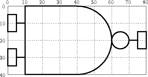
Figure 3.6: Primitive Composition of a NAND Gate
These nine primitives are all tagged with a unique alphanumeric name generated by the procedure dr_generate_tag. The tag consists of the string comp, followed by the type of the gate which, in turn, is followed by the serial number for that gate. All these elements of the tag are separated by underscores. Therefore all the primitives comprising the eighth NAND gate will be tagged with the string comp_nand_8.
The Tcl procedures which build all the gates are contained in the draw.tcl module. As an example of such a procedure, consider the code fragment in Figure 3.7. The colour and width variables are all determined from the resource database. The dr_wires_not procedure draws and tags all the wires connecting the ports to the component body and the NOT circle at the end of the gate. The dr_ports procedure draws the ports of the component; input ports are represented by green rectangles and output ports by red rectangles. The ports of a component are given additional tags to identify them as special parts of a component which can be connected to netlists. The parameters of both of these procedures consist of the component tag and the coordinates of the primitives they are to construct.
Note that all the canvas primitives which make up a component are given the tag component. This tag permits the implementation to quickly distinguish a component primitive from a netlist primitive on the canvas and lets the implementation identify components during operations which have components as their targets.
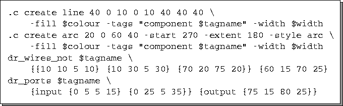
Figure 3.7: Tcl Code to Build a NAND Gate
In order to reduce code duplication, one procedure is responsible for producing both NAND and AND gates, depending upon its parameters. Therefore, the actual source code for constructing gates is a little more complicated than that presented in Figure 3.7. Currently, the interface is limited to creating the eight gates mentioned in Chapter 2. In order to extend the GUI to support other gates or higher level devices such as decoders and multiplexers, the draw.tcl module will have to be modified accordingly to support the construction of the new devices using the canvas primitives.
Upon construction of the gate, it is immediately moved from its origin in the upper left of the canvas to the current location of the mouse pointer on the canvas. Because canvas updates are buffered, the user will not notice the gate being drawn initially in the upper left corner of the canvas before it is moved to the current mouse location. A binding is established so that the motion of the mouse will cause the component to move across the canvas. The GUI employs gridded placement so that the component will move in discrete steps across the canvas so as to preserve their alignment with the canvas grid lines. This makes it easier to place and align the components. The synchronous motion of the component with the mouse is broken when the user presses the leftmost mouse button which affixes the component to its current position on the canvas.