Layout Editor
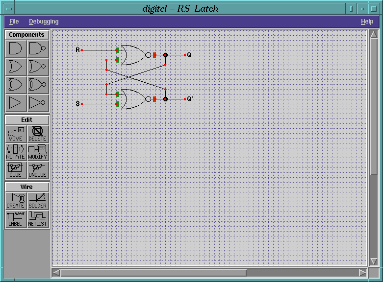
Using the layout editor, the user can layout and hookup different types
of logic gates. The Components section of the toolbar on the left
of the display offers the user a choice of eight logic gates which may
be placed anywhere at any 90 degree orientation on the workarea grid.
The Edit toolbar section provides operations which let the user
modify, delete or group entities on the layout workarea. The
Wire offers features which let the user interconnect the various
components together and to label the netlist in preparation for
simulation.

Signal Display
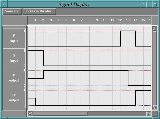
The signal display shows both the input and output signals for the
circuit in the layout workarea. A signal is displayed for each netlist
that the user has named using the Label feature in the
Wire section of the toolbar. The user may modify input
signals using the mouse and subsequently simulate the circuit to
display the appropriate output signals. The type of each signal
(input,output or unknown) is determined automatically by the interface.

![[Home]](/~donald/images/home.gif)
![[DigiTcl]](/~donald/images/digitcl.gif)
 Donald Craig
donald@cs.mun.ca
Last modified:
Tue Apr 8 18:41:22 NDT 1997


![[Home]](/~donald/images/home.gif)
![[DigiTcl]](/~donald/images/digitcl.gif)
 Donald Craig